Which version?
This Tutorial was written with iText 7.0.x in mind, however, if you go to the linked Examples you will find them for the latest available version of iText. If you are looking for a specific version, you can always download these examples from our GitHub repo (Java/.NET).
When we talk about low-level content in iText documentation, we always refer to PDF syntax that is written to a PDF content stream. PDF defines a series of operators such as m for which we created the MoveTo() method in iText, lfor which we created the LineTo() method, and S for which we created the Stroke() method. By combining these operands in a PDF (or by combining these methods in iText) you can draw paths and shapes.
Let’s take a look at a small example:
-406 20 m
406 20 l
S
This is PDF syntax that says: move to position ( X = -406 ; Y = 20 ), then construct a path to position ( X = 406 ; Y = 20 ); finally stroke that line – in this context, “stroking” means drawing. If we want to create this snippet of PDF syntax with iText, it goes like this:
canvas.MoveTo(-406, 20)
    .LineTo(406, 20)
    .Stroke();
That looks easy, doesn’t it? But what is that canvas object we’re using? Let’s take a look at a couple examples to find out.
Drawing lines on a canvas
Suppose that we would like to create a PDF that looks like Figure 2.1.
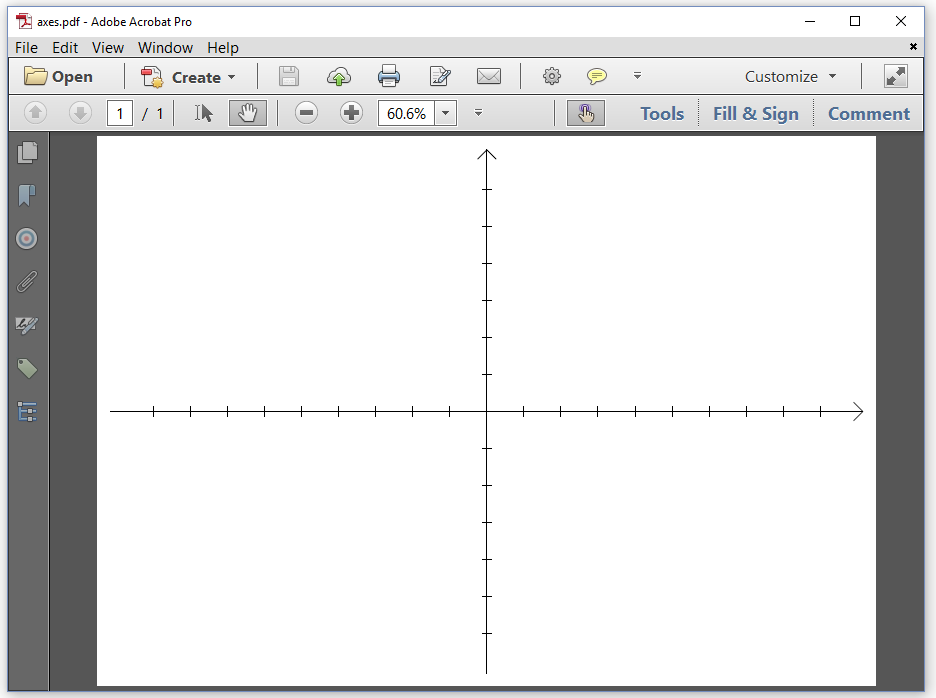
This PDF showing an X and Y axis was created with the Axes example.
Let’s examine this example step by step.
var fos = new FileStream(dest, FileMode.Create);
var writer = new PdfWriter(fos);
var pdf = new PdfDocument(writer);
var ps = PageSize.A4.Rotate();
var page = pdf.AddNewPage(ps);
var canvas = new PdfCanvas(page);
// Draw the axes
pdf.Close();
The first thing that jumps out is that we no longer use a Document object. Just like in the previous chapter, we create a Stream (line 1), a PdfWriter (line 2) and a PdfDocument (line 3) but instead of creating a Document with a default or specific page size, we create a PdfPage (line 5) with a specific PageSize (line 4). In this case, we use an A4 page with landscape orientation. Once we have a PdfPage instance, we use it to create a PdfCanvas (line 6). We’ll use this canvas object to create a sequence of PDF operators and operands. As soon as we’ve finished drawing and painting whatever paths and shapes we want to add to the page, we close the PdfDocument (line 8).
In the previous chapter, we closed the Document object with document.Close(); This implicitly closed the PdfDocumentobject. Now that there is no Document object, we have to close the PdfDocument object.
In PDF, all measurements are done in user units. By default one user unit corresponds with one point. This means that there are 72 user units in one inch. In PDF, the X axis points to the right and the Y axis points upwards. If you use the PageSize object to create the page size, the origin of the coordinate system is located in the lower-left corner of the page. All the coordinates that we use as operands for operators such as m or l use this coordinate system. We can change the coordinate system by changing the current transformation matrix.
The coordinate system and the transformation matrix
If you’ve followed a class in analytical geometry, you know that you can move objects around in space by applying a transformation matrix. In PDF, we don’t move the objects, but we move the coordinate system and we draw the objects in the new coordinate system. Suppose that we want to move the coordinate system in such a way that the origin of the coordinate system is positioned in the exact middle of the page. In that case, we’d need to use the ConcatMatrix() method:
canvas.ConcatMatrix(1, 0, 0, 1, ps.GetWidth() / 2, ps.GetHeight() / 2);
The parameters of the concatMatrix() method are elements of a transformation matrix. This matrix consists of three columns and three rows:
a  b  0
c  d  0
e  f  1
The values of the elements in the third column are always fixed (0, 0, and 1), because we’re working in a two dimensional space. The values a, b, c, and d can be used to scale, rotate, and skew the coordinate system. There is no reason why we are confined to a coordinate system where the axes are orthogonal or where the progress in the X direction needs to be identical to the progress in the Y direction. But let’s keep things simple and use 1, 0, 0, and 1 as values for a, b, c, and d. The elements e and f define the translation. We take the page size ps and we divide its width and height by two to get the values for e and f.
The graphics state
The current transformation matrix is part of the graphics state of the page. Other values that are defined in the graphics state are the line width, the stroke color (for lines), the fill color (for shapes), and so on. In another tutorial, we’ll go in more depth, describing each value of the graphics state in great detail. For now it’s sufficient to know that the default line width is 1 user unit and that the default stroke color is black. Let’s draw those axes we saw in Figure 2.1:
//Store a "backup" of the current graphical state
canvas.SaveState();

//Change the page's coordinate system so that 0,0 is at the center
canvas.ConcatMatrix(1, 0, 0, 1, ps.GetWidth() / 2, ps.GetHeight() / 2);

/When joining lines we want them to use a rounded corner
canvas.SetLineJoinStyle(PdfCanvasConstants.LineJoinStyle.ROUND);

//Draw X axis
canvas.MoveTo(-(ps.GetWidth() / 2 - 15), 0)
        .LineTo(ps.GetWidth() / 2 - 15, 0)
        .Stroke();

//Draw Y axis
canvas.MoveTo(0, -(ps.GetHeight() / 2 - 15))
        .LineTo(0, ps.GetHeight() / 2 - 15)
        .Stroke();

//Draw X axis arrow
canvas.MoveTo(ps.GetWidth() / 2 - 25, -10)
        .LineTo(ps.GetWidth() / 2 - 15, 0)
        .LineTo(ps.GetWidth() / 2 - 25, 10)
        .Stroke();

//Draw Y axis arrow
canvas.MoveTo(-10, ps.GetHeight() / 2 - 25)
        .LineTo(0, ps.GetHeight() / 2 - 15)
        .LineTo(10, ps.GetHeight() / 2 - 25)
        .Stroke();

//Draw X serif
for (int i = -((int)ps.GetWidth() / 2 - 61); i < ((int)ps.GetWidth() / 2 - 60); i += 40) {
    canvas.MoveTo(i, 5).LineTo(i, -5);
}
//Draw Y serif
for (int j = -((int)ps.GetHeight() / 2 - 57); j < ((int)ps.GetHeight() / 2 - 56); j += 40) {
    canvas.MoveTo(5, j).LineTo(-5, j);
}
canvas.Stroke();

//"Restore" our "backup" which resets any changes that the above made
canvas.RestoreState();
This code snippet consists of different parts:
-
Lines 2 and 43 show a best practice that we should use whenever we change the graphics state. First we save the current graphics state with the
SaveState()method, then we change the state and draw whatever lines or shapes we want to draw, and finally we use theRestoreState()method to return to the original graphics state. All the changes that we applied afterSaveState()will be undone. This is especially interesting if you change multiple values (line width, color,…) or when it’s difficult to calculate the reverse change (returning to the original coordinate system). -
Line 5 changes the current coordinate system so that (0, 0) is in the middle of the page instead of the bottom left corner
-
Line 8 changes the way that two or more lines are drawn when they interset as a result of multiple
LineTocalls. By default, lines will miter (the lines join in a sharp point) but this can be changed to bevel or round. We want our arrows to join using a rounded corner so we change the default line join value toROUND. -
Lines 11-13, 16-18 shouldn’t have any secrets for you anymore. We move to a coordinate, we construct a line to another coordinate, and we stroke the line.
-
Lines 21-24 and 27-30 are very similar to to what we did previously but these show you how to draw multiple lines in one operation. We construct the path of each arrow head with one
MoveTo()and twoLineTwo()calls. -
In lines 32-40, we construct small serifs to be drawn on both axes every 40 user units. Observe that we don’t stroke them immediately. Only when we’ve constructed the complete path, we call the
Stroke()method.
There’s usually more than one way to draw lines and shapes to the canvas. It would lead us too far to explain the advantages and disadvantages of different approaches with respect to the speed of production of the PDF file, the impact on the file size, and the speed of rendering the document in a PDF viewer. That’s something that needs to be further discussed in another tutorial.
There are also specific rules that need to be taken into account. For instance: sequences of SaveState() and RestoreState() need to be balanced. Every SaveState() needs a RestoreState(); it’s forbidden to have a RestoreState() that wasn’t preceded by a SaveState().
For now let’s adapt the first example of this chapter by changing line widths, introducing a dash pattern, and applying different stroke colors so that we get a PDF as shown in Figure 2.2.
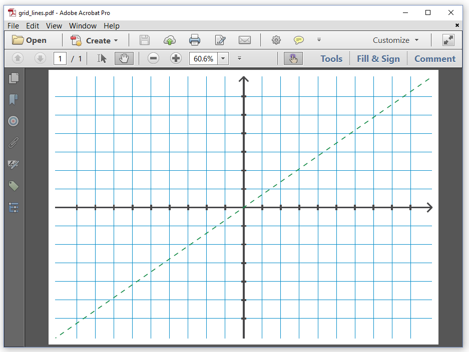
In the Gridlines example, we first define a series of Color objects:
//DeviceCmyk lives in iText.Kernel.Colors
var grayColor = new DeviceCmyk(0, 0, 0, 0.875f);
var greenColor = new DeviceCmyk(1, 0, 1, 0.176f);
var blueColor = new DeviceCmyk(1, 0.156f, 0, 0.118f);
The PDF specification (ISO-32000) defines many different color spaces, each of which has been implemented in a separate class in iText. The most commonly used color spaces are DeviceGray (a color defined by a single intensity parameter),DeviceRgb(defined by three parameters: red, green, and blue) and DeviceCmyk (defined by four parameters: cyan, magenta, yellow and black). In our example, we use three CMYK colors.
Be aware that we’re not working with the System.Drawing.Color class. We’re working with iText’s Color class that can be found in iText.Kernel.Colors.
We want to create a grid that consists of thin blue lines:
canvas.SetLineWidth(0.5f).SetStrokeColor(blueColor);
for (var i = -((int)ps.GetHeight() / 2 - 57); i < ((int)ps.GetHeight() / 2 - 56); i += 40) {
    canvas.MoveTo(-(ps.GetWidth() / 2 - 15), i)
            .LineTo(ps.GetWidth() / 2 - 15, i);
}
for (var j = -((int)ps.GetWidth() / 2 - 61); j < ((int)ps.GetWidth() / 2 - 60); j += 40) {
    canvas.MoveTo(j, -(ps.GetHeight() / 2 - 15))
            .LineTo(j, ps.GetHeight() / 2 - 15);

canvas.Stroke();
In line 1, we set the line width to half a user unit and the color to blue. In lines 2-9, we construct the paths of the grid lines, and we stroke them in line 10.
We reuse the code to draw the axes from the previous example, but we let them precede by a line that changes the line width and stroke color.
canvas.SetLineWidth(3).SetStrokeColor(grayColor);
After we’ve drawn the axes, we draw a dashed green line that is 2 user units wide:
canvas.SetLineWidth(2)
    .SetStrokeColor(greenColor)
    .SetLineDash(10, 10, 8)
    .MoveTo(-(ps.GetWidth() / 2 - 15), -(ps.GetHeight() / 2 - 15))
    .LineTo(ps.GetWidth() / 2 - 15, ps.GetHeight() / 2 - 15)
    .Stroke();
There are many possible variations to define a line dash, but in this case, we are defining the line dash using three parameters. The length of the dash is 10 user units; the length of the gap is 10 user units; the phase is 8 user units (the phase defines the distance in the dash pattern to start the dash).
Feel free to experiment with some of the other methods that are available in the PdfCanvas class. You can construct curves with the CurveTo() method, rectangles with the Rectangle() method, and so on. Instead of stroking paths with the Stroke() method using the stroke color, you can also fill paths with the Fill() method using the fill color. The PdfCanvasclass offers much more than a .Net version of the PDF operators. It also introduces a number of convenience classes to construct specific paths for which there are no operators available in PDF, such as ellipses or circles.
In our next example, we’ll look at a subset of the graphics state that will allow us to add text at absolute positions.
The text state
In Figure 2.3, we see the opening titles of Episode V of Star Wars: The Empire Strikes Back.
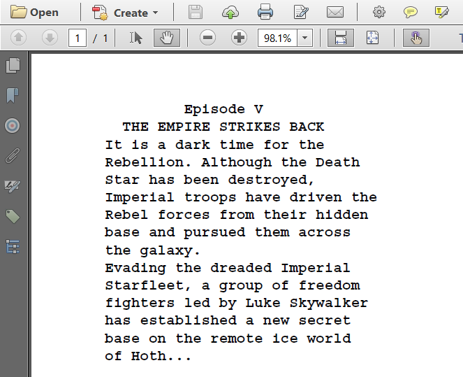
The best way to create such a PDF, would be to use a sequence of Paragraph objects with different alignments (center for the title, left aligned for the body text), and to add these paragraphs to a Document object. Using the high-level approach will distribute the text over several lines, introducing line breaks automatically if the content doesn’t fit the width of the page, and page breaks if the remaining content doesn’t fit the height of the page.
All of this doesn’t happen when we add text using low-level methods. We need to break up the content into small chunks of text ourselves as is done in the StarWars example:
var text = new List<string>();
text.Add("         Episode V         ");
text.Add("  THE EMPIRE STRIKES BACK  ");
text.Add("It is a dark time for the");
text.Add("Rebellion. Although the Death");
text.Add("Star has been destroyed,");
text.Add("Imperial troops have driven the");
text.Add("Rebel forces from their hidden");
text.Add("base and pursued them across");
text.Add("the galaxy.");
text.Add("Evading the dreaded Imperial");
text.Add("Starfleet, a group of freedom");
text.Add("fighters led by Luke Skywalker");
text.Add("has established a new secret");
text.Add("base on the remote ice world");
text.Add("of Hoth...");
For reasons of convenience, we change the coordinate system so that its origin lies in the top-left corner instead of the bottom-left corner. We then create a text object with the BeginText() method, and we change the text state:
canvas.ConcatMatrix(1, 0, 0, 1, 0, ps.GetHeight());
 canvas.BeginText()
     .SetFontAndSize(PdfFontFactory.CreateFont(iText.IO.Font.FontConstants.COURIER_BOLD), 14)
     .SetLeading(14 * 1.2f)
     .MoveText(70, -40);
We create a PdfFont to show the text in Courier Bold and we change the text state so that all text that is drawn will use this font with font size 14. We also define a leading of 1.2 times this font size. The leading is the distance between the baselines of two subsequent lines of text. Finally, we change the text matrix so that the cursor moves 70 user units to the right and 40 user units down.
Next, we loop over the different String values in our text list, show each String on a new line — moving the cursor down 16.2 user units (this is the leading) —, and we close the text object with the EndText() method.
foreach( var s in text) {
    //Add text and move to the next line
    canvas.NewlineShowText(s);
}
canvas.EndText();
It’s important not to show any text outside of a text object — which is delimited by the BeginText()/EndText() methods. It’s also forbidden to nest BeginText()/EndText() sequences.
What if we pimped this example and changed it in such a way that it produces the PDF shown in figure 2.4?
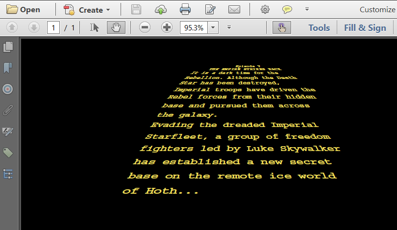
Changing the color of the background is the easy part in the StarWarsCrawl example:
canvas.Rectangle(0, 0, ps.GetWidth(), ps.GetHeight())
    .SetColor(iText.Kernel.Colors.Color.BLACK, true)
    .Fill();
We create a rectangle of which the lower-left corner has the coordinate X = 0, Y = 0, and of which the width and the height correspond with the width and the height of the page size. We set the fill color to black. We could have used SetFillColor(iText.Kernel.Colors.Color.BLACK), but we used the more generic SetColor() method instead. The boolean indicates if we want to change the stroke color (false) or the fill color (true). Finally, we fill that path of the rectangle using the fill color as paint.
Now comes the less trivial part of the code: how do we add the text?
//Get the length of the longest string
var maxStringWidth = text.Max(s => s.Length);

canvas.ConcatMatrix(1, 0, 0, 1, 0, ps.GetHeight());

var yellowColor = new DeviceCmyk(0, 0.0537f, 0.769f, 0.051f);

float lineHeight = 5;
float yOffset = -40;

canvas.BeginText()
        .SetFontAndSize(PdfFontFactory.CreateFont(iText.IO.Font.FontConstants.COURIER_BOLD), 1)
        .SetColor(yellowColor, true);

for (var j = 0; j < text.Count; j++) {
    var line = text[j];
    var xOffset = ps.GetWidth() / 2 - 45 - 8 * j;
    var fontSizeCoeff = 6 + j;
    var lineSpacing = (lineHeight + j) * j / 1.5f;
    var stringWidth = line.Length;
    for (var i = 0; i < stringWidth; i++) {
        float angle = (maxStringWidth / 2 - i) / 2f;
        float charXOffset = (4 + (float)j / 2) * i;
        canvas.SetTextMatrix(fontSizeCoeff, 0,
                angle, fontSizeCoeff / 1.5f,
                xOffset + charXOffset, yOffset - lineSpacing)
          .ShowText(line[i].ToString());
    }
}
canvas.EndText();
First, we find the length of the longest string to use in our calculations later (line 2). Next, we once more, we change the origin of the coordinate system to the top of the page (line 4). We define a CMYK color for the text (line 6). We initialize a value for the line height (line 8) and the offset in the Y-direction (line 9). We begin writing a text object. We’ll use Courier Bold as font and define a font size of 1 user unit (line 12). The font size is only 1, but we’ll scale the text to a readable size by changing the text matrix. We don’t define a leading; we won’t need a leading because we won’t use NewlineShowText(). Instead we’ll calculate the starting position of each individual character, and draw the text character by character. We also introduce a fill color (line 13).
Every glyph in a font is defined as a path. By default, the paths of the glyphs that make up a text are filled. That’s why we set the fill color to change the color of the text.
We start looping over the text (line 15) and we read each line into a String (line 16). We’ll need plenty of Math to define the different elements of the text matrix that will be used to position each glyph. We define an xOffset for every line (line 17). Our font size was defined as 1 user unit, but we’ll multiply it with a fontSizeCoeff that will depend on the index of the line in the text array (line 18). We’ll also define where the line will start relative to the yOffset (19).
We calculate the number of characters in each line (line 20) and we loop over all the characters (line 21). We define an angle depending on the position of the character in the line (line 22). The charXOffset depends on both the index of the line and the position of the character (line 23).
Now we’re ready to set the text matrix (line 24-26). Parameter a and d define the scaling factors. We’ll use them to change the font size. With parameter c, we introduce a skew factor. Finally, we calculate the coordinate of the character to determine the parameter e and f. Now that the exact position of the character is determined, we show the character using the ShowText()method (line 27). This method doesn’t introduce any new lines. Once we’ve finished looping over all the characters in all the lines, we close the text object with the EndText() method (line 30).
If you think this example was rather complex, you are absolutely right. I used it just to show that iText allows you to create content in whatever way you want. If it’s possible in PDF, it’s possible with iText. But rest assured, the upcoming examples will be much easier to understand.
Summary
In this chapter, we’ve been experimenting with PDF operators and operands and the corresponding iText methods. We’ve learned about a concept called graphics state that keeps track of properties such as the current transformation matrix, line width, color, and so on. Text state is a subset of the graphics state that covers all the properties that are related to text, such as the text matrix, the font and size of the text, and many other properties we haven’t discussed yet. We’ll get into much more detail in another tutorial.
One might wonder why a developer would need access to the low-level API knowing that there’s so much high-level functionality in iText. That question will be answered in the next chapter.